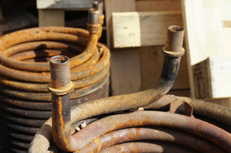
This heat exchanger is the common type used in most industrial applications. It contains a large shell enclosing several tubes, and its main purpose is to exchange heat between two fluids, gas or liquid, with different temperatures. One fluid stream passes through the tubes while another passes through the shell to trade their heat energies. There are instances when you might find a fixed tube-sheet exchanger where the tubes are permanently fixed or positioned inside the shell. Alternatively, you can find a U-tube or floating head exchanger; this is one where the tubes are easily removable to allow easy cleaning or replacements in case of any damage. Shell and tube heat exchangers come in various shell designs and different heat designs, but their working principle is the same, and here is how they work.
What is a Shell and Tube Heat Exchanger?
A heat exchanger is process equipment that aids heat transfer between two different fluids at different temperatures. A shell and tube heat exchanger is industrial equipment where two working fluids exchange their temperatures through thermal contact. The temperature difference between the fluids in the shell and the tubes is the driving force making the temperature exchange possible. These devices are compact in design, easy to fabricate, maintain, clean, and provide excellent heat exchange.
How Shell and Tube Heat Exchangers Work
The working principle of these heat exchangers is quite simple. This makes them the ideal and most popular types of heat exchangers in most industries. The shell and the tubes both have their inlets and outlets. So, depending on which side you choose to house which temperature, one fluid will flow inside the tubes and the other inside the shell. While these fluids are flowing, they exchange their heat through thermal contact. Meaning that the hot fluid gains the coolness of the cold fluid while the hot fluid gains heat from the hot fluid.
Therefore, one hot fluid enters the shell or the tubes through an inlet nozzle and leaves through the outlet nozzle as cold fluid. Ultimately, the other fluid will become hot and leave the outlet nozzle as hot fluid. The heat transfer in this heat exchanger depends on the amount of exposed surface area. This is determined by the number of thermally conductive metal tubes. The fluid flow in the shell and tube heat exchanger can be crossflow or parallel.
An increase in the number of tubes passes increases the heat transfer coefficient. And to increase the heat transfer between these two fluids, you must increase the fluid turbulence in the shell and tube side flow. You can achieve this by installing baffles and a turbulator inside the shell and tubes.
The Regulations And Standards
Shell and tube heat exchangers rarely have pressure-relief valves for fire exposure. This is because the vapours quickly flow to the next pressure vessel, where they get discharged. This mechanism is made possible by the two-thirds rule, which says:
- For commensurate low-pressure equipment, a complete tube failure isn’t a workable eventuality when the low-pressure side design equals to or exceeds two-thirds of the high-pressure side design pressure. If there are any minor leagues, they can rarely result in an overpressure of the low-pressure side during an operation. If your heat exchanger satisfies the above rule, then you will not need a relief valve on the low-pressure side of the equipment, provided these incidents are true:
- The hot fluid isn’t too hot to boil the cold-side fluid at the design pressure.
- There aren’t check valves, automatic control valves or block valves on the low-pressure inlet or outlet piping systems that could potentially isolate the exchanger.
- According to operating procedures, you must isolate the high-pressure side before the low-pressure side.
- According to operating procedures, you must drain the exchanger immediately after removing it from service. Furthermore, the exchanger has to remain drained while not in use or service.
The Basic Components of Shell and Tube Heat Exchangers
These heat exchangers have two major parts; the shell side and the tube side. The shell side consists of the body flange, nozzles, shell, cover, and saddle support. The Tube Side consists of the channel, body flange, nozzles, cover, tube sheets and tube bundle.
During fabrication, the layout designer or the process equipment manufacturers in Gujarat can freely rotate the tube side nozzle concerning the shell-side nozzles when there is only a single shell-side pass. However, the possible rotation is inhibited when there are two or more shell-side passes. If the heat exchanger’s operation isn’t affected, you may place the shell-side nozzles longitudinally on the shell. On the other hand, the pipe or tube configurations design must allow for the correct flow conditions at nozzles. This will provide a well-supported or flexible system that meets the manufacturers’ allowable stress.
Shell and tube heat exchangers are the convenient and mostly preferred types for most industries. Their main advantage is that they provide the largest heat transfer surface per unit volume and weight using a minimum number of connections. In addition, they are versatile and can easily meet any heat transfer service.
